|
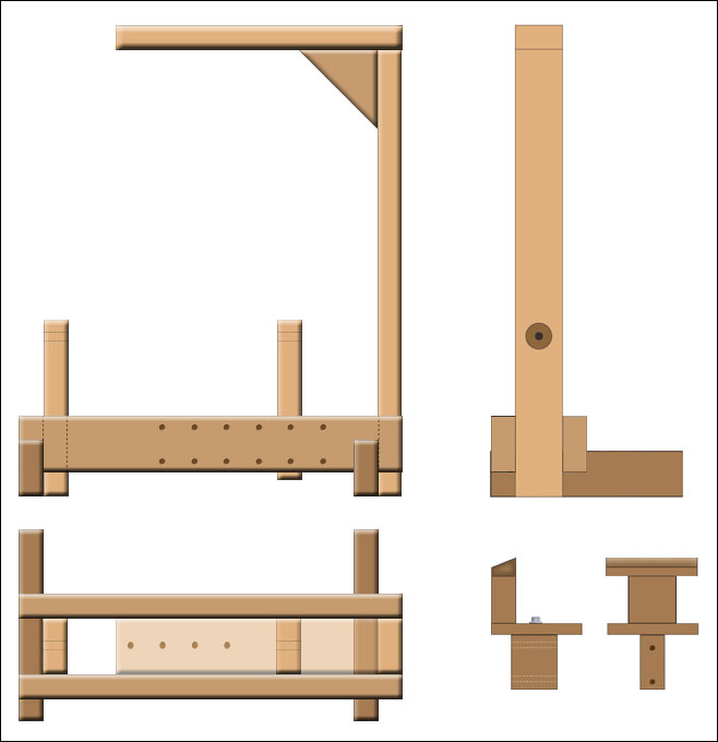
Lathe Layout:
Dimensions & Cut List:
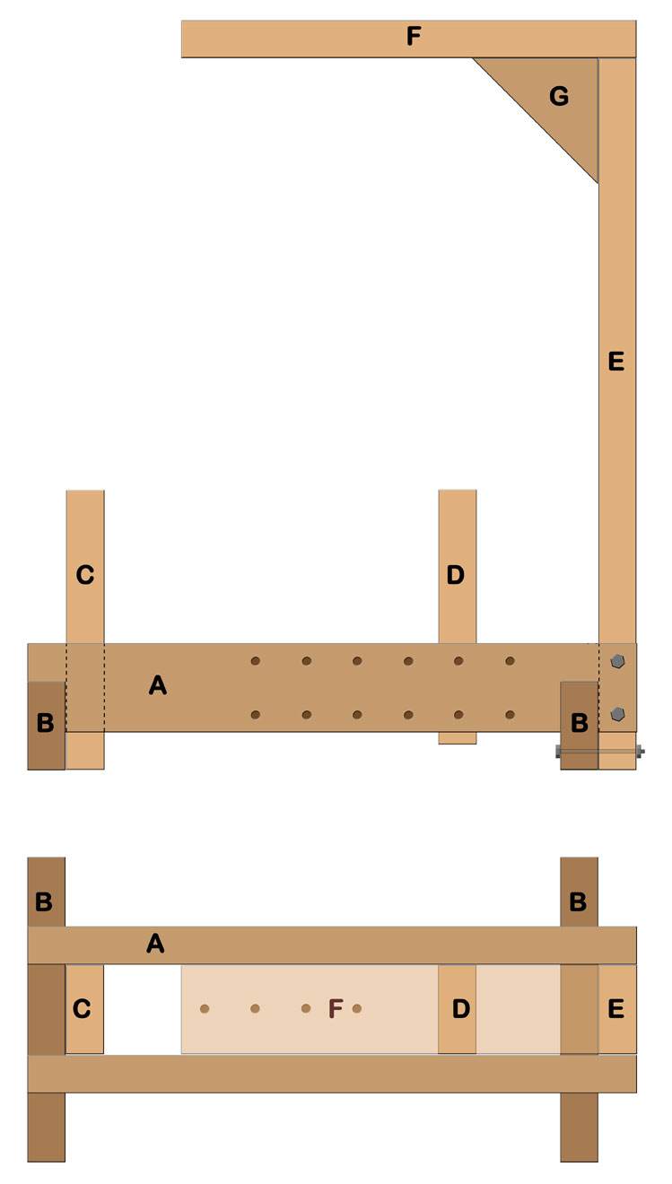
All from nominal 2x4 (1-1/2" x 3-1/2") stock.
A - Ways
24" (2)
B - Base
12" (2)
C - Fixed Left Tailstock 11"
D - Movable Right Tailstock 10"
E - Riser Beam
28"
F - Cross Beam
18"
G - Gusset
5"
Parts A, B, F & G = 95"
Parts C, D & E = 49"
General Construction Notes:
- 2x4's should be clear (or
nearly so) and very straight - especially with no twist.
- Base unit
(parts A, B & C) are assembled with 2-1/2" x #8 deck screws and
wood glue. Pilot holes should be pre-drilled to prevent splitting.
-
Clamp pieces in position then drill.
- Movable tailstock (D) is cross
drilled to match holes in ways and pinned in place with 2 - 3/8" x 8"
bolts with the threads cut off.
- Upper unit (parts E, F & G) are
screwed & glued like base unit was.
- Holes in Ways (A) are 2" on
center beginning 9" from left end - 3/8" diam.
- Holes in cross beam
(F) are 2" on center beginning 1" from left end
- Riser Beam
(E) is bolted to
base for portability with 2 - 3/8" x 7" bolts and 1 - 3/8" x 5" bolt.
The Building Process:
Begin by sawing two 2x4's into the nine pieces as shown above. A
nice touch is to round the tops of parts C & D and now is a good time to
drill the holes in those two pieces for the lathe centers.
Lathe Centers: I had good luck using
a medium duty gate
pintle (1/2"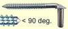 diameter) for the adjustable lathe center and a 1/2" x 3 lag bolt for
the fixed center. Bore a slightly undersized hole through the tail stock
upright, heat the pintle or lag
bolt with a propane torch (holding it in Vice Grips) and quickly screw it into the
hole. This burns some decent threads into the hole. While the screw is
still warm rub some bee's wax on it for lubrication. One of the
first turning projects on my lathe was to turn a wood handle to slip
over the 'handle' end of the pintle. I filed a nice, smooth, bluntish
point on the working end of the screw. This setup worked well for a lot
of years.
diameter) for the adjustable lathe center and a 1/2" x 3 lag bolt for
the fixed center. Bore a slightly undersized hole through the tail stock
upright, heat the pintle or lag
bolt with a propane torch (holding it in Vice Grips) and quickly screw it into the
hole. This burns some decent threads into the hole. While the screw is
still warm rub some bee's wax on it for lubrication. One of the
first turning projects on my lathe was to turn a wood handle to slip
over the 'handle' end of the pintle. I filed a nice, smooth, bluntish
point on the working end of the screw. This setup worked well for a lot
of years.
This is also a good time to drill the tailpiece
securing holes in the ways. Easiest way is the clamp the ways together and
use a drill press to bore through them at the same time - nicely
aligned. Mark and cross drill the tail stock (D) to match all those
holes you just drilled in the ways.
Notch the ways to fit
over the base pieces (B). Assemble the base section securing everything
in place with clamps. When you have it all lined up and square,
drill one pilot hole at a time and put in a deck screw. By going at it
one screw at a time you give yourself multiple opportunities to check
and re-align the base unit. The way I drill these kinds of pilot holes is
to first drill using a small (~1/8") bit to almost the depth of
the screw, then use that hole as a guide to enlarge the hole with a bit
that will allow the screw to just slide through the hole without
snagging. Finally, use a countersink bit to allow the screw head to be
flush with the surface. Three steps that go a lot faster if you have
more than one hand drill but I usually just change bits - over and over.
Now, drill the holes in the upper cross beam. These holes give
you multiple spots along the length of your turning to fasten the cord
or strap that wraps around your work-piece.
Assemble the upright pieces (E, F & G) with clamps and screw them
together as you did the base unit. It would be a good idea to remove the
gusset and apply some good wood glue and re-assemble it. The screws will
make it unnecessary to clamp that awkward shaped piece.
Just
three more holes to drill; two crosswise through the ways and
lower end of the upright, and one through the very lower end of the
upright and the base piece - see the drawing. By bolting the two main
units together rather than screwing and gluing, you can easily take the
lathe apart for transport.
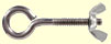
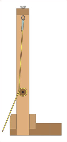
The only thing left before you can
begin turning your first piece is the cord or strap that makes the
whole thing work. To create the reciprocating action you can use a metal
spring, perhaps a section of a screen door spring, or a piece of bungee cord.
This recoiling device fastens to the screw-eye and the wrapping cord or
strap fastens to
it, coming down to wrap once around your
work-piece, and then continues down to a loop or better, a flat board
that acts as a treadle. A nice touch is to round over the front edge of
the front way to help reduce wear on the cord or strap.
In the
lower right corner of the Layout image is my idea of how one might make
an all-wood tool rest from the left-over pieces of 2x4. Its base fits
between the ways and can be adjusted left and right to align with the
holes in the ways. The horizontal piece is fastened to that base by a
bolt with a nut that is imbedded in the base. This allows the tool rest
to rotate laterally. You may well come up with a better way to do this
but what I've presented is very similar in function to the tool rest
I've used on my treadle lathe for years.
Using the Spring Pole Lathe:
The biggest tip I can offer is to keep your lathe tools really
sharp. On some of my tools I have ground a shallower bevel and that
seems to work well especially on green wood. It does take a few minutes
to coordinate foot action with a very slight backing-off of the tool on
the spring's return stroke, then a slight moving forward of the tool on
the down stroke. This movement become second nature quickly.
If
you have any questions please use the contact page and I'll do my best
to help you out. I hope you enjoy using your new lathe!
Steve
|