NAVIGATION EQUIPMENT:
I plan on using a couple of navigation tools on this boat;
primarily a chart and compass and as backup and entertainment, two apps on
an Android tablet. I'll have purchased a
Ritchie Reverse-card rowing compass and am looking forward to having a
compass that reads the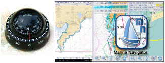 direction the boat is traveling even though you are facing the stern.
My main electronic navigation device is an older Samsung Note 10.1 tablet. I
have decided to use two apps; Marine Navigator, for route planning and
navigation and LD-Log for course tracking. Both apps are fully integrated
with the tablet's GPS capability. My thought is that during a full day or
two of rowing I may welcome a bit of useful diversion.

ELECTRICAL SYSTEM:
You wouldn't think that a rowboat would need an electrical system
but since I expect that my August trip will include some after dark rowing I
will be installing a 360 degree navigation light. And while I'm at it I'll
make sure there is enough power to keep a tablet with navigation and
tracking apps charged. Training rows will most likely take place on nearby
Indian Lake which has OK cell coverage but the area of the north shore of
Lake Michigan where I plan on doing the August trip has very limited
coverage but I'll want to keep a phone charged anyway.
Electrical Loads analysis:
| Load Description |
Amps |
Volts |
Watts |
Amps @ 40V |
Hours of Use |
AmpHours Used |
| Navigation Light |
0.11 |
12 |
1.3 |
0.03 |
12 |
0.36 |
| Android Tablet |
0.5 |
5 |
2.5 |
0.06 |
12 |
0.72 |
| Cell Phone |
0.25 |
5 |
1.25 |
0.03 |
12 |
0.36 |
| |
|
|
|
|
Total AHrs Used > |
1.44 |
| |
|
|
|
|
Battery Reserve: 64% |
|
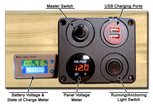
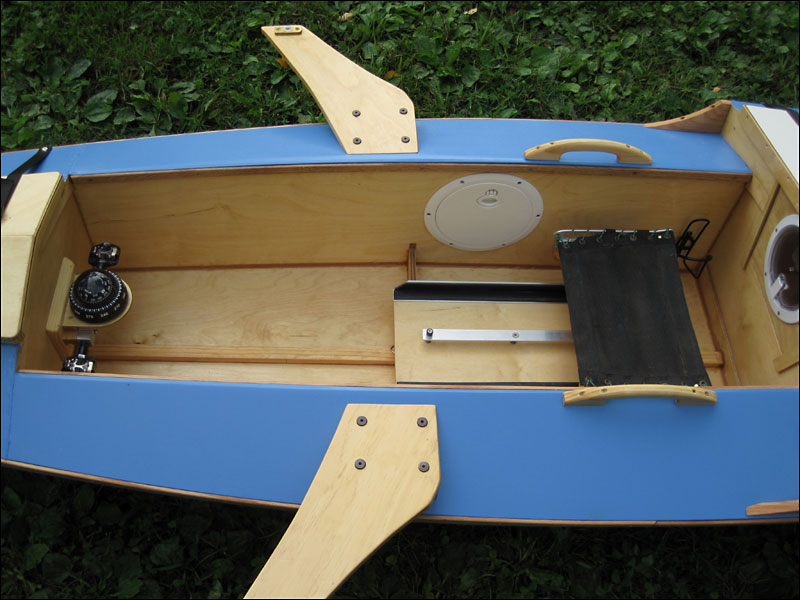
The power source is a 40 volt, 4 Amp-Hour lithium Ion
battery running through a DC to DC converter down to 12 volts for lights
then reduced further to 5 volts for device charging. The versatile and
powerful Greenworks batteries power our mower, trimmer and a electric
chainsaw as well as our Bose PA system. The battery base, battery and a
15-Amp Drok DC to DC converter will be mounted in the port cockpit
flotation/storage compartment. It is connected to a remote power panel that
will be mounted in the cockpit.
-
The meter on the left indicates the battery voltage
and % full; as you can see, the battery is currently full at 41.6 Volts.
-
Master Switch: Cuts power from the battery to the
converter.
-
USB Charging Ports - 2 x 2.1 Amp 5-volt charging
ports. 4.2 Amps total capacity. There is a waterproof cover on the port.
-
Panel Voltmeter: Indicates output from the DC/DC
converter, available for charging and lights.
-
Light Switch: Turns on/off the wired but removable
running/anchoring light.
Navigation/Anchoring Light:
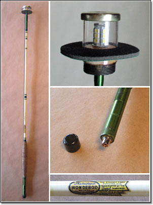
I've put together a lightweight removable light for use when rowing after
sundown and night anchoring. My Dad had a really nice Wonder-rod fly fishing
rod that was crying out to be reused for something useful. I don't fish and
had tried to sell the rod at a garage sale with no success. I used the
lower, handle section and a few inches of the middle part as a strong, light
shaft for the light.
The light is made up of an 18-LED
Landscape Light Bulb that produces 350 lumens in a 360 degree pattern. I
used a single one of these LED segments as a power-on indicator for a remote
camera and it is easy to see it even in daylight 125 yards away.
The fishing rod is totally hollow so wiring it was easy. I installed a
female RCA connector in the bottom end of the handle and it mates to a wired
male connector in a 5'8" ID aluminum mounting base. The base is located
flush with the starboard side deck forward of the cockpit. There is a black
disk just below the LED level to minimize the amount of light that will
shine down into the boat.
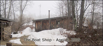
CONSTRUCTION -
FINALLY:
It is nearly spring here in Michigan's Upper Peninsula with daytime
temperatures near 40°
F. That makes it possible to heat up the shop and finally get to work on
building this boat. 4/2/2019
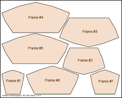
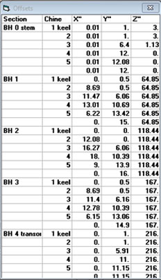
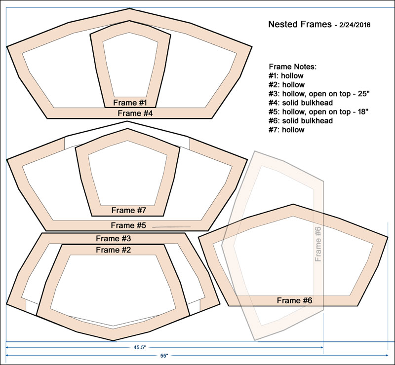
- Frames: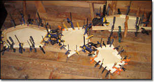
3/29/2019 - The frames are made from two layers of 1/4" Baltic birch
plywood; the only good, flat, waterproof plywood available locally. It is
heavier than real marine plywood but it has 5 plys and waterproof glue.
There are zero voids and as a test I have boiled a scrap of this plywood for
days with no delamination.
I transferred the frame layout to the plywood and cut around each piece with
a saber-saw then cleaned up the outlines with a fine-tooth blade in my old
1930's 12" Craftsman band saw. Today I epoxied half of the pairs together -
ran out of clamps (68), and will laminate the rest of them tomorrow. Doing
the epoxy work in the (warmer) house shop.
.
- Strongback: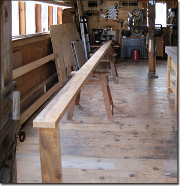
4/2/2019 - Today I finished the last of the frame laminating so it was time
to put together the strongback on which the boat will be built. I'm reusing
the beam I've used for all three of our SOF boats but because this boat has
practically no overhang at the bow and stern I needed to make the strongback
much longer. I added four feet to each end of the original 10' beam. It is
screwed to two sawhorses and two end supports which are in turn screwed to
the floor. The top of the beam is flat and level and immovable. I'll measure
and mark the frame locations next. I had a fire in the shop's woodstove and
it got up to 55°
in there today - very comfortable for the kind of work I was doing.
- Stringers/Gunwales:
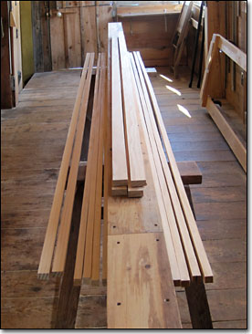
4/3/2019 - For months it seems, I have been trying to decide how heavily to
build this boat. One of the main considerations is what dimensions should
the keel, stringers and gunwales be. Too large and the boat gets heavier
than it needs to be; too small and the integrity and shape of the boat can
suffer. Today I finalized the dimensions for those long pieces and ripped
them from some 10' long, clear New Zealand pine using a thin-kerf blade in a
circular saw with its fence.
The sizes:
Keel 1-1/8" x 3/4"
Lower stringers 3/4" x 3/4"
Upper stringers 7/8" x 3/4"
Gunwales 1-3/4" x 3/4"
When these are paired up and scarfed end to end they will be about 19'-6"
long and quite unmanageable. A good job for tomorrow.
.-
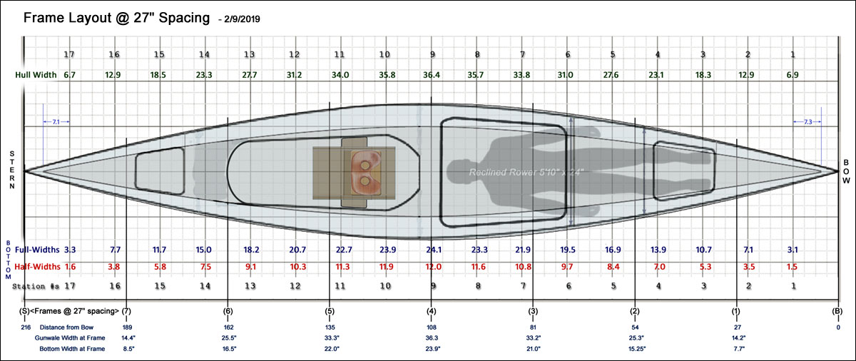
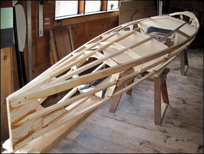
Setting up the frames: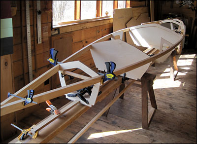
4/9/2019 - It's starting to look a little like a boat. I have the frames
clamped in position on the strongback and have temporarily clamped the
gunwales in place. This helps with decisions about whether to refine the
boat's shape at this point and I could see how much trimming I needed to do
of the stringer locations to make sure the boat remains straight.
I like the overall shape and will check a few of the dimensions to be sure
that for instance, I can fit in the cockpit comfortably. At that point the
boat is about 36" wide but the cockpit is only 20" wide. In theory the
smaller the cockpit area the safer the boat will be since in the event of a
capsize the cockpit is the only area that would take on water (assuming that
the hatches are closed securely).
With the rest of the boat acting as flotation any water that gets into the
cockpit would empty completely when the boat is righted - no bailing, just
crawl back in over the side and get back to rowing.
- More frame work: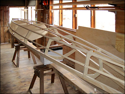
4/14/2019 - The gunwales and stringers are installed with screws
(no glue) at this point so that I could remove the frame from the strongback
and confirm that the hull has sufficient rocker. A little scary since I
suppose it is possible that the whole thing could kind of slide out of shape
but it all held together remarkably well and Sue and I could easily flip it
over. There is about 1-1/2" of rocker at each end and that looks about right
for this hull shape.
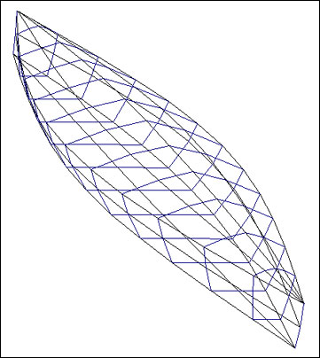
The flat bottom looks unusual but according to Colin Angus a long narrow
hull, sharp angles at the chines, and moderate rocker will combine to
eliminate the need for a drag-inducing outer keel or skeg. To ensure that I
don't lose the rocker I'll remove each screw and glue the joints with the
boat in this position, supported in the middle with the ends kind of hanging
there. I have checked the hull for straightness since it is off the
strongback and all is well.
4/27/2019 - Boat building is sharing time with spring homestead chores like
brush cutting (before the birds build nests) and firewood cutting. Yesterday
we were able to drive in to our house and shop for the first time since
December which makes supply transport more convenient.
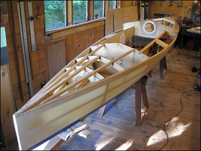
The photo is of the stern of the boat, looking forward.
The frame is upright and I have installed the aft deck stringers and am in
the process of designing and building the hatch opening in that deck. I have
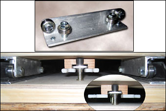
mounted one of the rigger base plates (where the oar lock extensions will
mount) in the frame and will install the other today.
I have been in and out of the boat a few times adjusting the sliding seat
position. It looks like I'll fit OK in the cockpit but it will be a
different experience rowing in that narrow (20" wide) space. Kind of cozy
feeling. The fore and aft location is established but I'll wait until I can
fit the riggers and oar locks before deciding on seat height.
- 'On-the-fly' engineering - as usual:
5/9/2019 - I climbed into the 'cabin' the other day just to be sure
it would be comfortable and it felt quite a bit too low. Plenty long enough
and good elbow room but the original plan didn't allow enough height in the
shoulder area to easily roll over. By laying a yardstick across the gunwales
and a bit of fiddling around I determined that another 3" height would be
nice. So, at the risk of increasing windage, the boat's susceptibility to
cross-winds, I designed a solution that involved adding 8' long, skinny
triangular pieces to the tops of the gunwale in the cabin area.
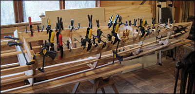
The additions are made up of two layers of 5/16" thick solid pine paneling
boards laminated using some small frame extensions above the gunwales. Hard
to explain but here is a photo of yet another clamping extravaganza. I ended
up adding about 3-1/2" height at the center frame tapering down to nothing a
foot or so from the bow.
On a related subject I'm working on a different hatch design for the cabin.
The original plan had a fairly large lift-off hatch for loading stuff into
the 'hold' but it was lacking in ease of getting from the cockpit into the
cabin while afloat. More on that as the scheme develops...
- The bottom is on: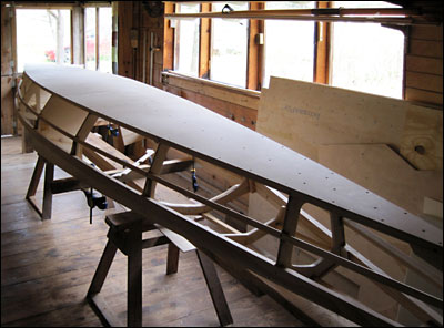
5/26/2019 - I managed to get the whole bottom out of one piece of 1/4"
Baltic Birch plywood by laying the sheet on the bottom of the framework and
tracing the bottom shape. Not much waste, which is good and bad. Bad because
I count on scraps for a lot of the smaller bits and pieces. The bottom is
screwed down and epoxied in place. I've chosen to do a couple of modified
butt joints where the panel sections meet. The mid-boat joint has radically
beveled 1/4" plywood butt blocks on the inside and will have recessed
fiberglass and epoxy reinforcement on the bottom. The joint at the aft end
is only about 6" long so will be only backed up with fiberglass and epoxy
top and bottom.
I have flipped the boat upright and am currently working on the cockpit
sides. It is a bit of a challenge establishing locations for the side
hatches and water bottle/snack cubbies on either side of the rowing
position. I'm working on that today and will hopefully have a photo of the
final cockpit layout soon.
- Cockpit sides installed: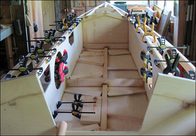
6/14/2019 - It seems like it has been quite a while since I posted any
progress on the boat. I have been working on it most days for a few hours
but at this stage progress seems slow. I have done a bunch of little things
that were on my boat-to-do list but of course I have added lots of jobs to
the list too.
The cockpit sides are fitted and glued into place - finally. I had some
logistical decisions to make; like where exactly do I want the
storage access hatches and electrical system panel mounted. Not about where
do you think they should go but really, where will they work the best.
Anyway, that's all done now and it's time to move on the the next things on
the list; designing and fitting the cabin and storage area hatches. Next
time ...
Closing in on time to skin the hull:
7/6/2019 - Well, I missed my projected 4th of July launch date - by quite a
bit, and my to-do list is still pretty long. I have been
designing/fabricating covers for the main hatch. Considerations included
ease of entrance to the cabin while on the water, increasing cabin height
without adding a lot of weight and ensuring that the hatch is reasonably
water-tight. I want the cabin dry if I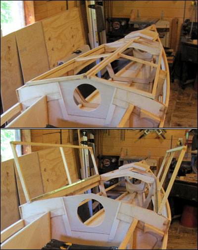 decide to sleep in there or just rest and relax out of the rain but also
that enclosed area is a major flotation compartment - as long as it is well
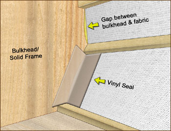
sealed. Creating water-tight compartments on a skin-on-frame boat is not as
easy as on more conventional designs as the skin flexes between the chines.
I came up with some flexible vinyl seals when rebuilding my Mobjack Bay
kayak last fall and am using that techniques on this boat as well. Although
it would be nice if those seals worked 100% but I'll be happy if they just
keep out a flood of water in the event of a capsize.
decide to sleep in there or just rest and relax out of the rain but also
that enclosed area is a major flotation compartment - as long as it is well
sealed. Creating water-tight compartments on a skin-on-frame boat is not as
easy as on more conventional designs as the skin flexes between the chines.
I came up with some flexible vinyl seals when rebuilding my Mobjack Bay
kayak last fall and am using that techniques on this boat as well. Although
it would be nice if those seals worked 100% but I'll be happy if they just
keep out a flood of water in the event of a capsize.
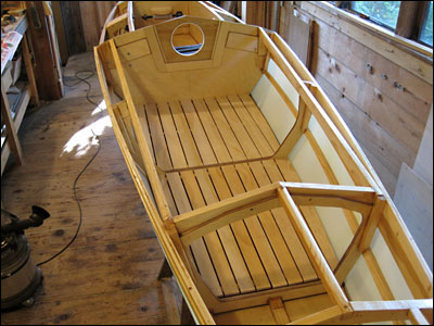
In the photo you can see how the cabin hatch covers open. They swing up on
long piano hinges and will be covered with the same polyester fabric as the
rest of the boat to keep them light. Also in the photo is the lift-out
companionway panel that will have a pop-out waterproof port that can also be
screened to hopefully keep mosquitoes out of the cabin but still allow
ventilation.
I have sanded all frame surfaces and am ready to oil the whole thing -
today's project. Once the frame is dry I'll mount some of the parts that are
easier to do without the skin on then, finally, it will be time to flip the
boat and stretch on that skin.
A few more photos ...
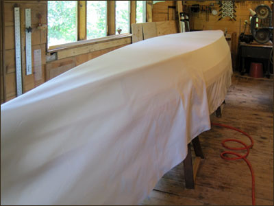
Skinning the hull:
7/15/2019 - Finally, the hull is covered with the 9 oz. polyester
fabric I purchased from George Dyson back when there was still snow on the
ground. This is my fourth skin-on-frame boat so the skinning went pretty
well. First I stretched the 20' long piece of fabric very tightly lengthwise
over the inverted hull using C-clamps, strong rope and a couple of hooks
screwed into the walls at either end of the boat. A trucker's hitch at each
end allowed me to really tension the fabric.
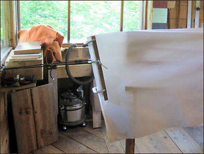
Once everything was tight and lined up I pulled the fabric tight across the
hull and put in a few stainless steel staples about 3" apart. Then, I ducked
under the boat, pulled the fabric pretty tight and put in a few on the other
side. Over and over, working my way toward the ends about 8" at a time. A
lot of knee scuffing since the tensioning ropes prevented walking around the
ends of the boat. After this first round of stapling the skin was pretty
tight. I removed a few staples where there might be a loose spot and
re-stapled while pulling out any wrinkles. When it all looked good I went
back and pulled the skin tighter placing a couple more staples between each
one - in the end about five hundred staples. It would not have been so much
fun without my trusty $30 Surebonder #9600 pneumatic stapler. Not a single
jam or misfire!
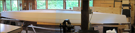
Waterproofing:
7/16/2019 - I applied a coat of Helmsman Spar Varnish to the sides of the
hull today. This serves as the first layer of waterproofing and once dry
allows me to mask around the edge of the bottom. Masking tape won't stick to
the bare fabric at all.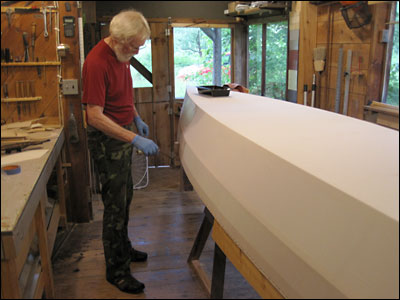 Once masked I applied a skim coat of PL Premium to the bottom to improve its
abrasion resistance. I let the PL cure for a couple of days then rolled on a
couple of coats of 'Blazing Blue' satin 100% Acrylic Latex House & Trim
paint. I'd go with semi-gloss next time; it looks almost flat but at least
the slight surface irregularities don't show much.
Once masked I applied a skim coat of PL Premium to the bottom to improve its
abrasion resistance. I let the PL cure for a couple of days then rolled on a
couple of coats of 'Blazing Blue' satin 100% Acrylic Latex House & Trim
paint. I'd go with semi-gloss next time; it looks almost flat but at least
the slight surface irregularities don't show much.
I need to iron out a few wrinkles that have mysteriously appeared in the
sides of the hull. My guess is that they were caused by some shrinkage or
loosening caused by either the bottom coatings or more likely, by the
varnish.
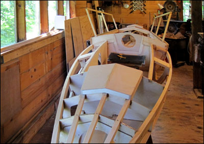
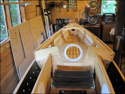
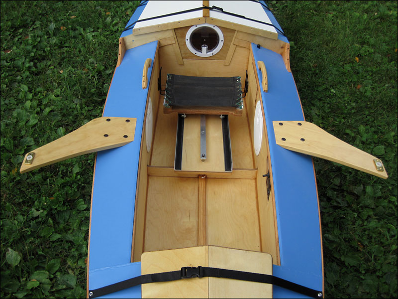
8/4/2019 - Here are a few photos of the boat as of today. I have installed
the electrical system and the frames of the pop-out hatches as well as built
a four-piece floor for the cabin.
 The
floor will solve two problems; eliminate my being jabbed in the back by the
frame in the middle of the cabin and it will help keep my sleeping gear dry.
This at the price of decreasing the effective height in the cabin by a
little more than an inch. It had to be done to make the cabin usable. The
floor will solve two problems; eliminate my being jabbed in the back by the
frame in the middle of the cabin and it will help keep my sleeping gear dry.
This at the price of decreasing the effective height in the cabin by a
little more than an inch. It had to be done to make the cabin usable.
8/5/2019 - Today I (we) flipped the boat bottom up once again. I decided to
put one more coat of paint on the bottom and install three oak rub strips -
one full length down the center and two shorter ones on either side. This
arrangement works well on the dory and has saved the bottom from wear when
on the trailer and when beaching.
8/11/2019 - Flipped again! Finally decided on a color scheme for the boat;
Darkish blue for the bottom, light blue for topsides, medium blue for decks
and off-white for the cabin hatches. Here's how it looks today.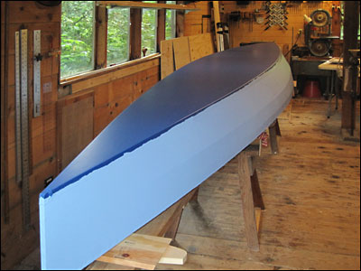
Most of those squiggles will disappear when I remove the masking tape - I
hope. I'm using the same 100% acrylic latex trim paint for the whole boat
except that the sides and decks are semi-gloss. I bought the 1-1/4" x 3/8"
oak material for the bottom rub strips and will install them tomorrow. I may
plane them down to 1/4" thick depending on how they look when laid out on
the bottom.
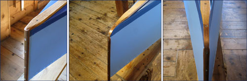
8/17/2019 - Time to install the bottom rub strips. It would be nice if this
is the last time the boat has to be bottom up. As time has gone on the boat
has become harder to rotate - it is heavier and also, there are fewer easy
places to grab onto during the flipping process.
Here are the rub strips installed and a photo of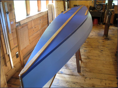 how they meet the copper stem and stern pieces.
Oh, I forgot to mention those little guys. I bought a piece of 1/2" copper
tube and a non-ferrous saw blade for the ShopSmith, made a simple ripping
jig and cut the tube roughly in half lengthwise. In the process I also
created an incredible amount of gold glitter which covered nearly every
horizontal surface in the shop. Pause for extended vacuuming session ...
STERN BOW BOW
Detail
Skinning the decks: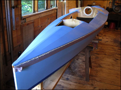
8/20/2019 - Things are moving right along now. Once the boat was upright I
covered the decks with the same 9 oz. polyester fabric used on the rest of
the boat. Again, lots of stainless steel staples and a fair bit of trimming
with the hot knife. This is really the first time I've been able to see how
the boat's lines look since the open framework is mostly hidden now. As of
this evening I have applied three coats of paint to the decks. Contrary to
what it looks like in the photo the decks are a slightly darker color than
the topsides. I'll probably put on at least one more coat to even out the
fill of the fabric's weave. Next up is to install the coamings around the
hatches and cabin.
Final Fit-out: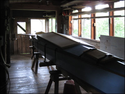
8/29/2019 - Yes, there is an end to this boat-building project.
Over the last few days I have installed all those pieces that have been
patiently waiting for their chance to become part of the boat. It is ready
for the water and its official emergence to the world outside the boat shop.
Saturday, August 31st is the next likely day weather wise for the launching.
In the mean time the boat is hanging out in the shop one last time and when
I'm not rowing, I'll be out in the woods cutting this winter's firewood or
hiking or playing music but not boat building for a while. It has been a
fun, creative adventure and although I'll have lots to do around the
homestead, I will miss those hours among the shavings and sawdust.
Our storage building (repurposed airplane hangar) is full - of boats. This
will make number five. But the shop will feel so empty ...
Done:
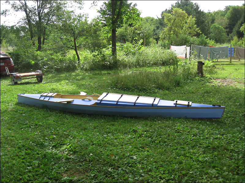
9/2/2019 - Here are a few photos of the boat as it emerged from the shop
onto the grass and on the water at nearby Indian Lake. Click on any of these
photos to see a larger view (Use your 'back' button to return).
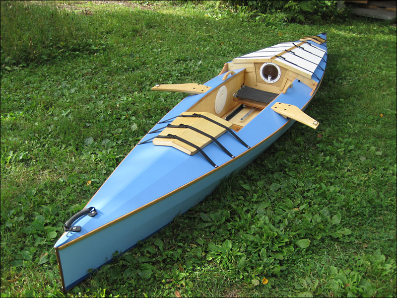
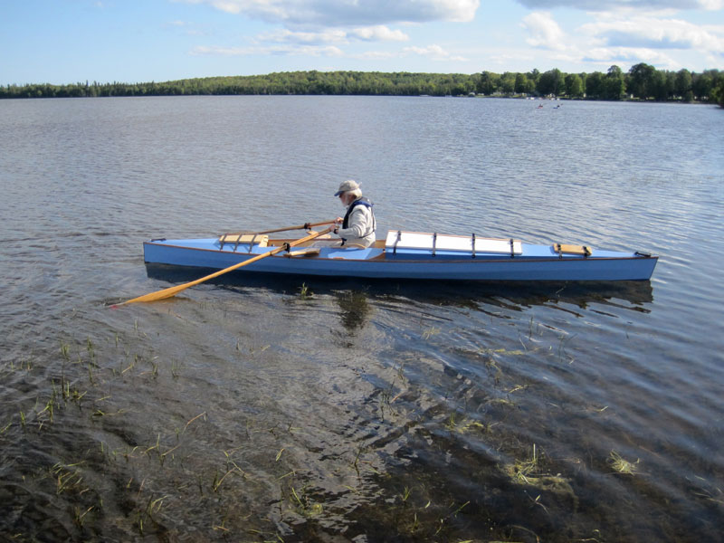
Short Rowing Report:
9/2/2019 - The boat sits on its lines - with the help of a 2-gallon water
bag in the bow compartment. On a normal trip there would be some gear up
forward and the water ballast wouldn't be needed. It draws less than three
inches of water and is super stable. The wing riggers necessitate having the
boat a foot or so from the dock but stepping down into the boat was no
problem at all.
I put the oars in place and pushed off. The first couple of pulls on the
oars were one of those 'Oh yes!" moments. The boat quickly got up to speed
and tracked straight as an arrow. I got carried away with the feeling of
power and control and ended up in a lily-pad bed across the bay before I
knew it. I spent the next half hour relearning how to judge distance covered
on the water - among more lily pads and reeds than I care to admit. The test
run was a fun experience and I look forward to some longer trips yet this
fall.
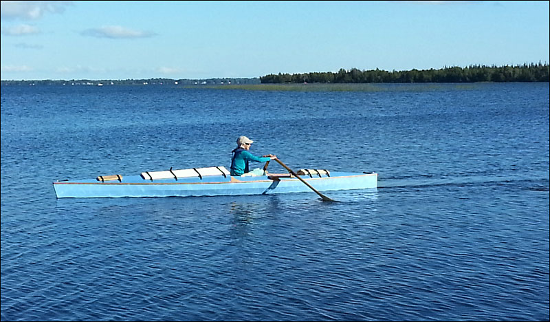
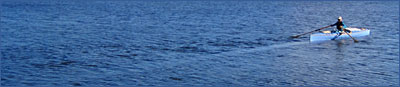
Sue got in and took it for a spin. She just rowed away without working at it
at all and tracked straight as you can see here:
I'll get a few more photos as we get some more time on the water.
Potential adjustments:
1. drill a 1/2" hole in each rigger near the hull to temporarily 'store'
the oars.
2. raise the oarlock sockets about 1/2" to improve knee clearance and help
prevent oar 'catches' on the recovery stroke.
3. modify (again) the looms of my 8'-4" oars to work better in the Gaco oar
locks.
4. make up a rack to allow carrying Sue's Kayak on the trailer.
Follow-up:
9/6/2019 - I did number 1 above and also added small aluminum clips that
hold the blades of the oars above the gunwale.
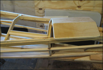
9/7/2019 - Finished the kayak rack today. It is made up of two wooden
support units that rest on the bottom of the boat; one in the forward end of
the cockpit and one that is in the forward hatch. These things have fairly
large feet to spread out the load and ensure that they stay in place. Here
are a few photos of the units in place but the kayak isn't strapped down
yet.
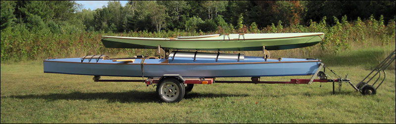
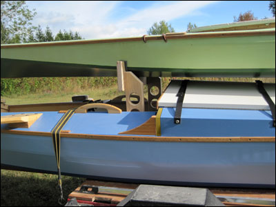
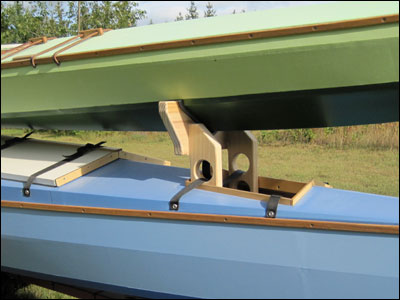
When we get to the launch site the kayak gets lifted off and the two rack
units get tossed in the back of the car.
By the way, the trailer is an inexpensive utility trailer we bought from
Northern Tool many years ago. I extended the tongue 8' and recently added a
support extension on the rear. I removed the second leaf of the springs to
soften the ride. The trailer pulls nicely behind our 2007 Prius and with
this load only knocks the mileage down from 50 mpg to around 47 mpg.
Notes:
8/29/2019 - Done for now!
The Spring of 2020 Update is here:

.
|